AUTOTRANSFORMERS
|
|
|
Note: This document is a continuation of
Understanding Early Street Light Circuits.
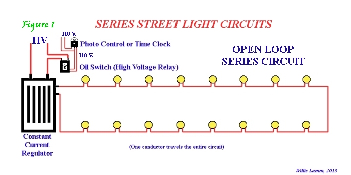
Most early street light systems ran on series circuits. The reasons for their use and how they worked are more completely discussed in the feature, Understanding Series Circuits, however I'll briefly recap their basic operations and why shunts were needed for lamps connected to these circuits. In series circuits all of the lamps are daisy-chained in series as illustrated in Figure 1. The circuits operated on high voltage but limited amperage, allowing the use of smaller, far less expensive conductor wires. The actual voltage across each lamp was generally less than 50 volts but the potential voltage produced by the regulator could often exceed 2,000 volts. Figure 1 shows the basic layout of a series circuit. Simply put, current leaves the regulator, passes through each lamp in turn, then returns to the regulator.
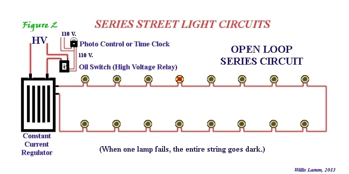
If a lamp were to fail, the circuit would be interrupted and the string of lights would go dark, as illustrated in Figure 2.
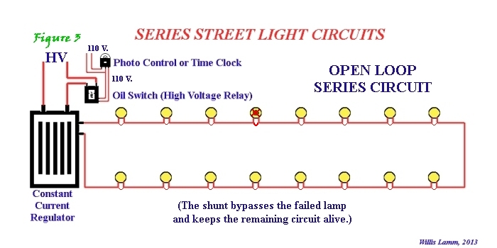
To prevent the string from going dark, a shunt would be placed in parallel across each lamp. When the lamp eventually failed, the shunt would allow current to bypass the failed lamp and keep the remainder of the lamps lit, as illustrated in Figure 3.
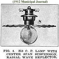
The earliest widely-used electric street lamps were arc lamps. (Please see Understanding Arc Lamps for a more detailed discussion on arc lamps.) Eventually arc lamps gave way to Mazda type incandescent lamps. However both types of lighting primarily relied on series circuits, so the same basic approaches for shunting applied to either technology.
A simple early means of shunting each lamp was through the use of autotransformers. Current would be passed through the primary windings of the autotransformer whether or not the lamp itself was working, and thus kept the circuit alive. The lamp was supplied from the secondary windings of the autotransformer.
There were, however, two distinctive disadvantages associated with autotransformers. Autotransformers consumed some power themselves in order to operate, slightly decreasing the efficiency of the circuit and the number of lamps that could be supplied by a given regulator. When lamps failed, autotransformers would sometimes generate significant radio interference. In the late 1940s when mercury vapor lamps became popular, the ballasts used to operate the mercury vapor lamps also served satisfactorily as shunts. Furthermore these ballasts did not produce the same radio interference as autotransformers when lamps failed. These devices remain in service today on series circuits that supply mercury vapor lamps. |
 There was a definite advantage in having a distinctive piece of hardware in place that would both bypass a failed lamp and keep the voltage to the lamp socket from spiking to deadly levels when lamps were changed. Even with autotransformers installed inside incandescent luminaire bodies, the overall size and weight of those fixtures were less than that of similar use arc lamps.
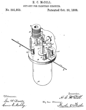
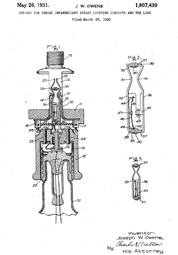
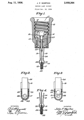
An early but effective design during the arc lamp era involved the magnetic cutout. The premise was simple. A magnetic solenoid was wired in parallel with the lamp. When the lamp failed, voltage across the solenoid would go high and the solenoid would attract a plunger that would close a toggle or knife switch. When the switch was thrown, the failed lamp would be effectively bypassed and the remaining lamps would stay lit. When a carbon electrode set in an arc lamp or a bulb in an incandescent lamp was replaced, the lineman would reset the magnetic cutout, once again placing that lamp back in the series. Magnetic cutouts worked well for arc lamps but sometimes created problems for incandescent lamps. If the cutout did not act quickly enough, a small lightning storm of high voltage could erupt in the burned out lamp that sometimes could damage the socket and luminaire. In an effort to improve the response of magnetic cutouts, engineers worked on miniaturizing the devices, often using the bayonet principle of the Jones Socket. |
|
|
| However as film type cutouts became more reliable, they were ultimately preferred over the slower-acting magnetic cutouts. |